
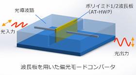
Thin wave plate suitable for optical circuits
Made of polyimide, it has excellent heat resistance and chemical resistance that can withstand soldering work.
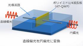
In addition, the material itself has a chemical structure that suppresses absorption at communication wavelengths, making it ideal for use in optical circuits (PLC).
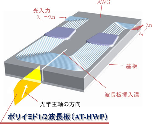
Modulators (Mach-Zehnder, QPSK) and low-loss optical circuit implementation on AWG are possible.
Feature
- Low insertion loss
- High heat resistance to withstand soldering work
- Since it is thin and easy to handle, it is ideal as a wave plate to be inserted into an optical circuit.
Application example
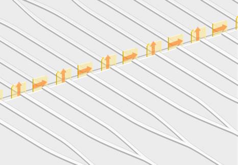
Application example to AWG
Example of application to integrated optical circuits
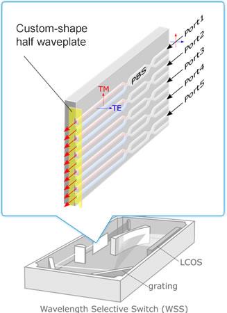
Example of polarization conversion for multiple ports
It can also be applied to multi-fiber connectors (MT) in multi-port optical circuits and polarization conversion in front ends of WSS.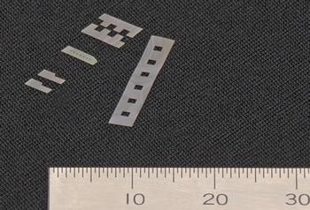
Example of application to a wavelength multiplexer/demultiplexer and the effect of eliminating polarization dependence by using a wave plate
Fig.2 Insertion loss spectra (a) before and (b) after inserting AT-HWPinto the waveguide gap.
(○: TE through ●: TM through □: TE cross ■: TM cross)
* Reference Y. Inoue, H. Takahashi, S. Ando, T. Sawada, A. Himeno, and M. Kawachi, J.LightwaveTechnol. 15, 1947 (1997).
Specification
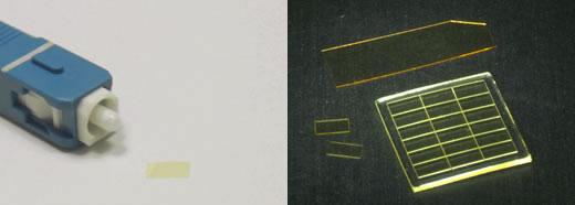
Lower left: Small wave plate (1×0.5mm)
Bottom right: Small wave plate 18 chips (1×0.5mm) on protective sheet
| half-wave plate | quarter-wave plate | |
|---|---|---|
| extinction ratio | ≥25dB | 0±1dB |
| optical axis | 45±1° | 0±1° |
| Design wavelength | 1550nm | |
| Thickness | 15±2μm | |
| size | 0.5×0.75 ±0.05 mm | |
Download materials
| Polyimide half-wave plate AT-HWP pamphlet | 679KB | download |
|---|---|---|
| Polyimide quarter-wave plate AT-QWP pamphlet | 665KB | download |
In addition, we handle various waveplates such as zero-order waveplates, large-diameter zero-order waveplates, zero-order waveplates (arbitrary wavelengths), multi-order waveplates, and achromatic waveplates. For more information, click here
 close up